ESD COMPLIANCE STANDARDS
ANSI/ESD S20.20
ESD ASSOCIATION STANDARD FOR THE DEVELOPMENT OF AN ELECTROSTATIC DISCHARGE CONTROL PROGRAM
WHAT THIS STANDARD GOVERNS
The program-level standard for ESD control in manufacturing and handling environments. S20.20 defines the requirements for an ESD control program — including flooring, grounding, personnel grounding, and compliance verification — and establishes the resistance limits and body voltage generation thresholds that all program elements must meet.
How We Address It
S20.20 is the governing document for every ESD flooring installation we perform. Our material selection, grounding design, and testing protocols are structured around S20.20’s requirements — not adapted after the fact. This means the flooring system is designed as a component of the facility’s broader ESD control program, not as an isolated installation.
We verify compliance through the specific test methods S20.20 references — STM 7.1 for resistance and STM 97.1 for walking body voltage — using calibrated instrumentation at the frequencies and electrode configurations the standard specifies. Results are documented in a format that maps directly to S20.20’s compliance verification requirements.
Our closeout documentation package is structured as an S20.20 compliance record, providing your ESD coordinator with the evidence needed to demonstrate that the flooring component of the program meets the standard’s requirements during internal audits and customer audits alike.
- S20.20 compliance verification report
- System resistance classification (conductive / dissipative)
- Walking body voltage test results per STM 97.1
- Resistance-to-ground measurements per STM 7.1
- Point-to-point resistance measurements
- Grounding system documentation and connection details
- Material technical data with resistance specifications
- Calibration certificates for all test instrumentation
IEC 61340-5-1
PROTECTION OF ELECTRONIC DEVICES FROM ELECTROSTATIC PHENOMENA — GENERAL REQUIREMENTS
WHAT THIS STANDARD GOVERNS
The international counterpart to ANSI/ESD S20.20. IEC 61340-5-1 defines ESD control requirements for facilities that operate under European or international compliance frameworks. For multinational operators building facilities in the U.S. — or U.S. facilities supplying international clients — compliance with this standard is frequently specified alongside or instead of S20.20.
How We Address It
The resistance limits and body voltage thresholds in IEC 61340-5-1 align closely with S20.20, but the compliance documentation expectations differ in structure and terminology. We’re experienced in delivering documentation packages that satisfy both standards simultaneously — essential for hyperscaler operators with facilities across multiple countries who standardize on a single ESD program specification.
When a project specification calls for IEC 61340-5-1 compliance, our test procedures, reporting format, and compliance verification documentation are adapted to match the standard’s specific terminology and structure. The testing itself is substantially identical, but the paper trail needs to speak the auditor’s language.
- IEC 61340-5-1 compliance verification report
- Resistance measurements per IEC test methodology
- Body voltage generation verification
- Documentation formatted to IEC compliance structure
- Dual-standard compliance report (when both specified)
ANSI/ESD STM 7.1
FLOOR MATERIALS — RESISTANCE TESTING
WHAT THIS STANDARD GOVERNS
The test method standard for measuring the electrical resistance of floor materials and installed flooring systems. STM 7.1 defines electrode configurations, applied voltages, measurement procedures, and environmental conditioning requirements for resistance-to-ground (RTG) and point-to-point resistance testing of ESD flooring.
How We Address It
Every ESD flooring installation we complete is tested per STM 7.1 at project completion. We perform resistance-to-ground measurements at the intervals and electrode placements the standard specifies — not at self-selected “representative” locations. Testing uses 5-lb cylindrical electrodes on the installed surface with the voltage and measurement timing parameters STM 7.1 requires.
We test at the environmental conditions present in the operating facility, not at laboratory-ideal conditions. STM 7.1 specifies that temperature and humidity be recorded at the time of measurement, and our test reports document these conditions alongside every resistance reading — because an auditor will look for them.
Results are mapped to floor plan locations so that your facilities team can identify the exact test point for any measurement in the report. This spatial documentation supports future retesting, maintenance planning, and audit defense.
- Resistance-to-ground (RTG) measurements mapped to floor plan
- Point-to-point resistance measurements mapped to floor plan
- Environmental conditions at time of each measurement
- Electrode configuration and applied voltage documented
- Pass/fail determination per S20.20 resistance limits
- Instrument identification and calibration certificate
- Test technician identification
ANSI/ESD STM 97.1
FLOOR MATERIALS AND FOOTWEAR — VOLTAGE MEASUREMENT IN COMBINATION WITH A PERSON
WHAT THIS STANDARD GOVERNS
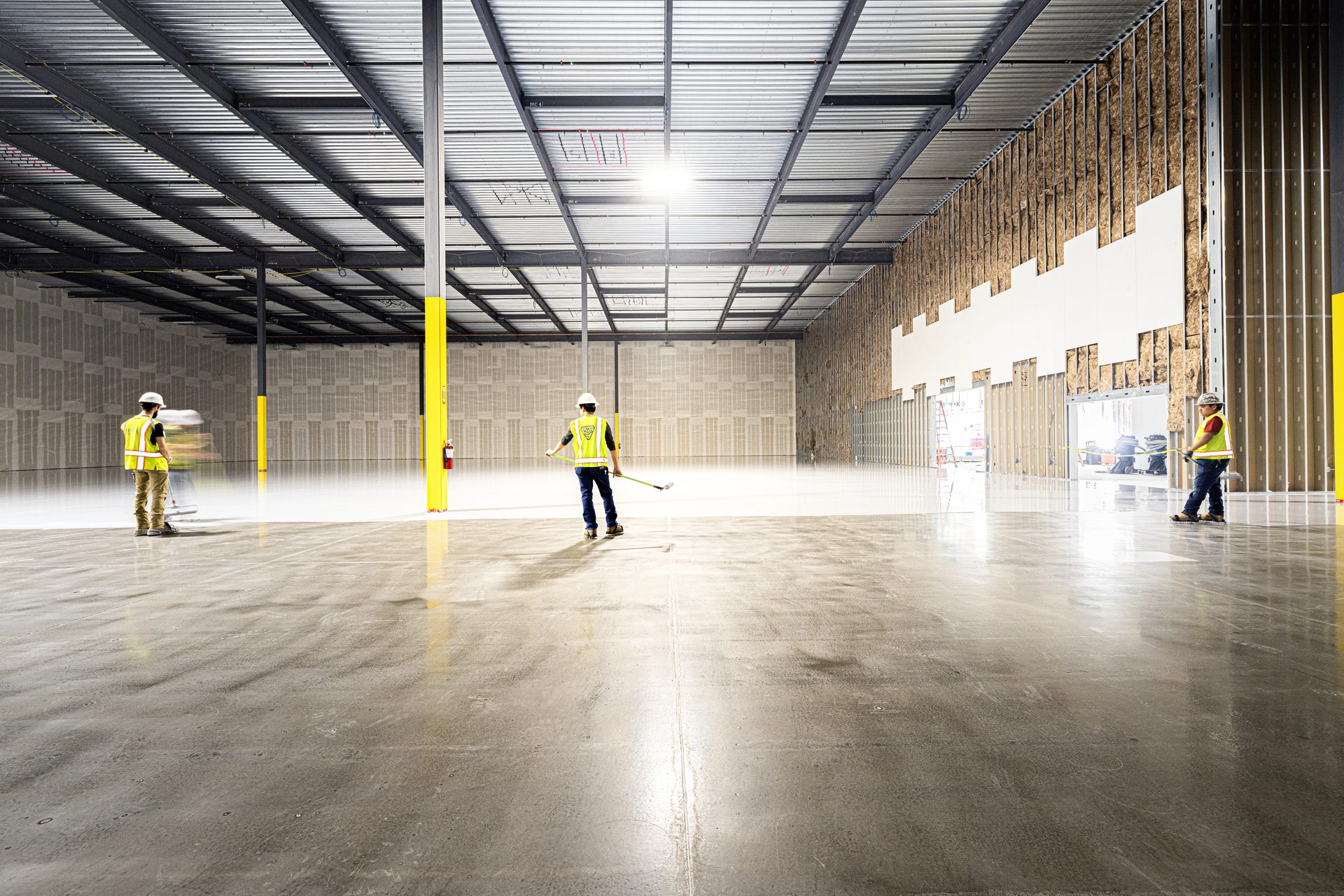
The test method for measuring the body voltage generated by a person walking on an installed flooring system while wearing specified footwear. STM 97.1 quantifies the actual electrostatic charge that accumulates on a person in the real operating environment — the number that determines whether the floor will protect sensitive components from ESD damage during handling.
How We Address It
Walking body voltage testing is performed on the installed floor using the footwear type specified for the facility’s ESD program — typically ESD-rated shoes or heel straps per S20.20 requirements. The test subject walks a defined path while body voltage is continuously measured, capturing the peak voltage generated under actual use conditions.
S20.20 requires body voltage below 100 volts for most ESD-sensitive environments, but many semiconductor and electronics manufacturing facilities specify tighter limits based on the HBM sensitivity of their components. We test to your facility’s specific threshold, not just the standard’s default, and document the applicable limit alongside the measured results.
This is the test that matters most to your ESD coordinator because it measures the actual risk to components — not a material property, but a system performance result that includes the floor, the grounding, the footwear, and the environment working together.
- Peak body voltage measurements (multiple walk paths)
- Footwear type and specification documented
- Walking path locations mapped to floor plan
- Environmental conditions (temp, RH) at time of test
- Pass/fail against facility-specific voltage threshold
- Pass/fail against S20.20 default (< 100V)
- Instrument calibration certificate
SUBSTRATE & MOISTURE TESTING
ASTM F2170
STANDARD TEST METHOD FOR DETERMINING RELATIVE HUMIDITY IN CONCRETE FLOOR SLABS USING IN SITU PROBES
WHAT THIS STANDARD GOVERNS
The primary test method for evaluating moisture conditions within a concrete slab before applying coatings, adhesives, or flooring systems. F2170 measures the internal relative humidity of the concrete at a specified depth using in-situ probes — providing a direct measurement of the moisture condition that will affect coating adhesion and system performance.
How We Address It
F2170 testing is performed on every project where a coating or overlay is applied to a concrete substrate. We drill test holes to 40% of the slab depth (for slabs drying from one side) or 20% of depth (for slabs drying from both sides), install in-situ RH probes, and allow equilibration for the minimum 72-hour period the standard requires before recording measurements.
Test hole frequency follows the standard’s requirements — a minimum of three holes for the first 1,000 square feet, plus one additional hole per 1,000 square feet thereafter. For large data center or manufacturing slabs, this means dozens of test points, each documented with location, depth, equilibration time, and measured RH.
When RH readings exceed the coating manufacturer’s threshold — typically 75% RH for epoxy systems, though manufacturer limits vary — we design and document a moisture mitigation system appropriate for the conditions. This isn’t a change order surprise. Moisture testing is performed early enough in the project sequence that mitigation is planned, specified, and budgeted before installation begins.
- RH readings mapped to floor plan by test location
- Drill depth documented per test hole
- Equilibration time documented (72+ hours)
- Ambient temperature and RH at time of reading
- Manufacturer’s maximum RH limit identified
- Pass/fail determination per manufacturer threshold
- Moisture mitigation recommendation (if required)
- Probe calibration verification
ASTM F1869
STANDARD TEST METHOD FOR MEASURING MOISTURE VAPOR EMISSION RATE OF CONCRETE SUBFLOOR USING ANHYDROUS CALCIUM CHLORIDE
WHAT THIS STANDARD GOVERNS
A surface-level moisture test that measures the rate of moisture vapor escaping from the top of a concrete slab over a defined period. F1869 (the “calcium chloride test”) has been the traditional moisture test in the flooring industry for decades and remains specified by some coating manufacturers and in some project specifications, though F2170 has become the preferred method for most engineered flooring systems.
How We Address It
When F1869 is specified, we perform the test per the standard’s requirements — sealed calcium chloride dishes placed on a clean, dry slab surface for 60-72 hours, with weight-gain measured to calculate moisture vapor emission rate (MVER) in pounds per 1,000 square feet per 24 hours. Test locations follow the same frequency protocol as F2170.
We typically recommend F2170 as the primary moisture test and offer F1869 as a supplementary or specification-required test. F2170 measures internal slab conditions directly, while F1869 measures only the surface emission rate, which can be influenced by ambient conditions and does not reflect the moisture condition deeper in the slab. Many coating manufacturers have moved to F2170 as their specified acceptance test.
When both tests are performed, results are presented together with the applicable manufacturer thresholds for each. This gives your engineer the complete moisture picture and supports specification compliance regardless of which standard was referenced.
- MVER results (lbs/1,000 SF/24 hrs) per test location
- Test location mapped to floor plan
- Exposure duration documented (60-72 hours)
- Ambient conditions during test period
- Manufacturer’s maximum MVER threshold identified
- Pass/fail determination
- Comparison with F2170 results (when both performed)
SURFACE PREPARATION & SLAB QUALITY
ICRI 310.2
SELECTING AND SPECIFYING CONCRETE SURFACE PREPARATION FOR SEALERS, COATINGS, POLYMER OVERLAYS, AND CONCRETE REPAIR
WHAT THIS STANDARD GOVERNS
The industry-standard guideline for specifying and evaluating the concrete surface profile (CSP) required for coating and overlay adhesion. ICRI 310.2 defines a scale of CSP 1 through CSP 10, from nearly smooth to heavily abraded, and provides visual reference comparisons (rubber profile chips) for field verification of surface preparation adequacy.
How We Address It
Every coating system has a manufacturer-specified CSP range for proper adhesion. ESD epoxy systems typically require CSP 2-4, achieved through diamond grinding or light shot blasting. Urethane cement systems often require CSP 3-5, achieved through aggressive shot blasting. We determine the required profile from the manufacturer’s technical data and prepare the surface to that specification — verified by comparison against ICRI reference chips in the field.
Surface profile is documented and photographed at representative locations before coating application begins. This pre-application documentation serves two purposes: it confirms that the substrate is properly prepared for the specified system, and it creates a defensible record that surface preparation met the manufacturer’s requirements — critical for warranty enforcement.
Inadequate surface preparation is the most common cause of coating failure. We invest the time and equipment in achieving the correct profile because every downstream performance metric — adhesion, resistance, durability, warranty validity — depends on what happens at the concrete surface before the first coat of material is applied.
- Target CSP range per manufacturer specification
- Achieved CSP documented by area
- ICRI chip comparison verification
- Pre-application surface photography
- Surface preparation method documented
- Adhesion test results (where specified)
- Contamination removal verification (oil, curing compounds)
ACI 302.1R
GUIDE FOR CONCRETE FLOOR AND SLAB CONSTRUCTION
WHAT THIS STANDARD GOVERNS
The American Concrete Institute’s comprehensive guide for the design, construction, and quality control of concrete floor slabs. ACI 302.1R classifies floors by use (from residential to heavy industrial), defines flatness and levelness tolerances (F-numbers), and establishes best practices for concrete placement, finishing, curing, and joint design that affect the performance of any flooring system applied over the slab.
How We Address It
ACI 302.1R is the reference we use to evaluate whether a concrete slab is suitable to receive a coating or overlay system. Before we install anything, we assess the slab for the conditions ACI 302.1R addresses — flatness, levelness, surface defects, joint condition, curing compound residue, and overall slab quality. These conditions directly impact the installed flooring system’s performance and appearance.
When we identify slab conditions that fall outside acceptable parameters — excessive waviness, poorly cut joints, surface contamination from curing compounds, or structural cracking — we document the conditions, report them to the project team, and recommend corrective action before proceeding. This early identification prevents downstream failures and change orders.
For new construction projects where we’re engaged during design, we provide input on slab specifications that affect flooring performance — curing methods compatible with subsequent coatings, flatness tolerances appropriate for the flooring system, and joint design that minimizes reflective cracking through the finished floor. Getting involved before the slab is poured is the highest-value intervention point for flooring system performance.
- Pre-installation slab condition assessment
- Flatness/levelness evaluation (F-number reference)
- Joint condition and layout documentation
- Surface defect and contamination report
- Corrective action recommendations (if required)
- Curing compound compatibility assessment
- Pre-pour specification input (new construction)