DATA CENTER FLOORING REQUIREMENTS
HYPERSCALE, COLOCATION & EDGE FACILITIES
Data center flooring operates in a zero-tolerance environment. A single ESD event can destroy server components, corrupt storage arrays, or trigger cascading failures across interconnected systems. Flooring in these facilities isn’t a finish — it’s a component of the electrical infrastructure, grounded and tested to the same standards as the rack-level ESD controls above it.
We install ESD flooring systems for hyperscale operators, colocation providers, and enterprise data centers across build-to-suit new construction, raised-floor retrofits, and white-space buildouts. Our systems integrate with the facility’s grounding architecture, meet ASHRAE environmental guidelines, and are installed within the compressed timelines that characterize data center construction.
ENVIRONMENTAL CONDITIONS
OPERATING PARAMETERS THAT GOVERN SYSTEM SELECTION
Data centers maintain controlled environments year-round — typically 64–80°F with relative humidity between 20–80% per ASHRAE A1 guidelines. These conditions affect coating cure schedules, moisture mitigation requirements, and long-term system performance. We design and schedule installations around your facility’s HVAC commissioning timeline.
Particulate control during installation is non-negotiable. Grinding, shot blasting, and coating operations generate airborne contaminants that can infiltrate adjacent live server environments. Our surface preparation and installation protocols include HEPA-filtered containment, negative-pressure enclosures, and sequenced operations that protect occupied white space.
Thermal cycling in data center environments is minimal compared to manufacturing or exterior applications, but mechanical loading from server racks, PDUs, and battery cabinets is concentrated and sustained. We specify coating systems with compressive strength ratings that exceed point-load requirements for fully loaded rack configurations.
Material systems are specified to meet sustainability and procurement compliance requirements common to hyperscale operators. We install low-VOC systems that qualify for LEED v4.1 IEQ credit contributions and provide Environmental Product Declarations (EPDs) for materials where available. For operators tracking embodied carbon or Scope 3 emissions across construction packages, we supply the material-level documentation your sustainability team needs to close out reporting requirements — not marketing sheets, but data formatted for your ESG framework.
| Parameter | Typical Range |
|---|---|
| Temperature | 64–80°F (ASHRAE A1) |
| Relative Humidity | 20–80% non-condensing |
| Point Loading | 2,000–3,500 lbs per rack position |
| Vibration | Low (generator rooms excepted) |
| Chemical Exposure | Battery electrolyte, coolant, cleaning agents |
| Traffic Type | Wheeled carts, pallet jacks, foot traffic |
| Cleanliness | ISO 14644 Class 8 or facility-specific |
| Sustainability | Low-VOC systems · LEED v4.1 IEQ eligible · EPD documentation available |
ESD COMPLIANCE & GROUNDING INTEGRATION
ELECTRICAL PERFORMANCE REQUIREMENTS FOR SERVER ENVIRONMENTS
ESD flooring in data centers must integrate with the facility’s grounding system, not operate as an isolated layer. We install conductive and dissipative systems that connect to the building’s telecommunications grounding bus bar (TGB) or common bonding network (CBN), verified at each connection point.
System resistance ranges are specified to match operational requirements — dissipative systems (1.0 × 10⁶ to 1.0 × 10⁹ ohms) for general server halls, conductive systems (< 1.0 × 10⁶ ohms) for environments handling exposed components. Walking body voltage generation is maintained below 100V per ANSI/ESD S20.20, verified by testing with calibrated instrumentation at completion.
Grounding is documented per connection point with resistance-to-ground measurements, conductor routing, and connection details recorded in the closeout package. This documentation supports the facility’s commissioning process and provides audit-defensible records for the life of the installation.
Closeout documentation is structured as a recertification baseline, not a one-time deliverable. The resistance maps, grounding records, and test data we provide at project completion become the benchmark your facility team references for annual ESD audits, tenant compliance verification, and system recertification. We offer scheduled re-testing services to verify long-term system performance and update baseline records — so when your next audit cycle arrives, the data package is already current.
- System resistance testing (RTG per ANSI/ESD STM 7.1)
- Walking body voltage verification (STM 97.1)
- Point-to-point resistance mapping
- Grounding conductor routing documentation
- Connection to TGB/CBN verified and recorded
- Post-installation compliance report (ANSI/ESD S20.20)
- Calibrated instrumentation certificates
- Annual re-testing and recertification baseline support
OPERATIONAL CONSTRAINTS
SCHEDULE, ACCESS & COORDINATION IN ACTIVE ENVIRONMENTS
Data center construction timelines are compressed by design. Hyperscale operators measure project schedules in weeks, not months. Flooring installation is typically sequenced between slab completion and raised-floor installation or equipment placement, with limited float in either direction. We staff for accelerated schedules with second and third shift capability.
In retrofit and expansion projects, installation occurs adjacent to live server environments. Containment protocols, vibration management, and access restrictions are coordinated with facility operations before mobilization. We work within your change management process and maintain communication with your NOC or facility operations team throughout.
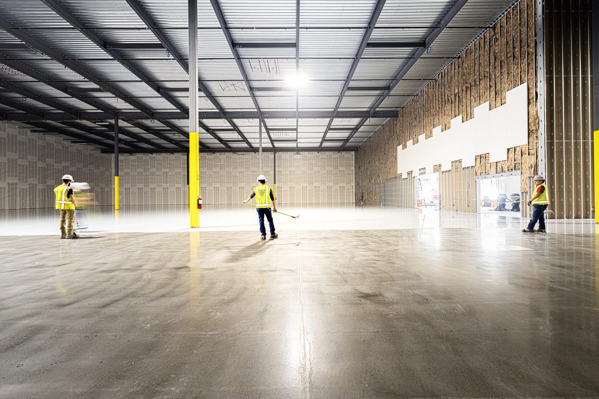
Multi-phase, multi-building programs are typical for hyperscale operators building campus-scale facilities. We deploy consistent crews and supervision across phases to maintain system uniformity — the floor installed in Building 4 matches Building 1, tested to the same specification, documented in the same format.
- HEPA containment for work adjacent to live environments
- Negative-pressure enclosures during surface preparation
- Vibration-restricted operations near active equipment
- NOC / facility ops coordination protocol
- Change management integration
- Multi-building crew consistency
- Accelerated schedule staffing (2nd/3rd shift)
- Phased turnover aligned to equipment placement
NUCLEAR & DOE FACILITY FLOORING REQUIREMENTS
POWER GENERATION, RESEARCH & SMR CONSTRUCTION
Nuclear facilities operate under a documentation regime that has no equivalent in commercial construction. Every material, every process, and every test result must be traceable, auditable, and defensible – not for the project closeout, but for the life of the facility. Flooring in these environments isn’t evaluated on appearance. It’s evaluated on whether the installation record can withstand NRC inspection twenty years from now.
We install flooring systems for nuclear power generation facilities, DOE research environments, and small modular reactor (SMR) construction sites. Our documentation practices, safety culture, and chain-of-custody protocols are designed for environments where regulatory scrutiny is the baseline condition, not the exception.
DOCUMENTATION & TRACEABILITY
NRC-GRADE RECORD-KEEPING FOR AUDIT DEFENSE
Every material that enters a nuclear facility flooring installation is tracked from manufacturer to installed location. Material batch numbers, lot codes, manufacturing dates, and shelf-life verification are recorded and cross-referenced to specific installation areas. This chain of custody creates the traceability record that NRC inspectors and DOE auditors require.
Test data is recorded with calibration traceability — every resistance measurement, every moisture reading, every thickness check is documented alongside the specific instrument used, its calibration date, and the technician who performed the test. There are no verbal approvals, no uncalibrated instruments, and no undocumented deviations.
Records are structured for long-term retrieval. Nuclear facility records don’t expire. We deliver closeout documentation in indexed, digitized formats organized for integration with your facility’s document management system. Thirty years from now, an auditor should be able to trace any installed square foot back to its material source, test results, and installer.
Our documentation practices are structured to align with ASME NQA-1 quality assurance requirements. Material traceability, inspection records, instrument calibration, nonconformance reporting, and corrective action documentation follow the controlled-document framework that NQA-1 establishes for nuclear facility applications. This isn’t a familiarity claim — it’s how we build the closeout package. When your QA team or an NRC inspector pulls a record, the format, traceability, and audit trail are already there.
Documentation is delivered as a living audit baseline, not an archived closeout binder. The structured record set — material traceability, calibrated test data, and nonconformance history — is formatted for direct integration into your facility’s ongoing audit and surveillance program. For operational facilities subject to periodic NRC inspection or DOE assessment, we provide re-testing and record update services that maintain the installation’s audit-defensible status across outage cycles and relicensing intervals.
- Material chain of custody (batch/lot/date/location)
- Manufacturer certifications and mill test reports
- Shelf-life verification for all time-sensitive materials
- Instrument calibration certificates per test event
- Technician identification per inspection record
- Deviation and nonconformance reporting
- Digitized closeout indexed for DMS integration
- Long-term retention format (30+ year retrievability)
- Periodic re-testing and audit baseline update services
SAFETY CULTURE & ACCESS PROTOCOLS
WORKING WITHIN NUCLEAR-GRADE SAFETY ENVIRONMENTS
Nuclear construction sites enforce layered security and safety protocols that exceed standard commercial construction by orders of magnitude. Badging, background checks, fitness-for-duty programs, and site-specific safety orientations are prerequisites before any crew member accesses the work area. We manage these requirements as part of our mobilization process, not as afterthoughts.
Safety culture in nuclear environments means stop-work authority is real. Every crew member understands that identifying a condition adverse to quality is not optional — it’s expected. Our field leadership is trained to operate in environments where a safety observation halts work until resolution, and where documentation of the stop-work event is itself a deliverable.
Radiological and hazardous material awareness is maintained for crews working in operational nuclear environments. While flooring installation typically occurs in non-radiological areas, proximity to controlled zones requires awareness training, adherence to boundary protocols, and coordination with the facility’s health physics team.
- Background investigation and badging coordination
- Fitness-for-duty program compliance
- Site-specific safety orientation completion
- Stop-work authority training and documentation
- OSHA 30 certification (all crew members)
- Radiological awareness training (where applicable)
- Boundary and access control coordination
- Health physics team interface protocols
ENVIRONMENTAL & PERFORMANCE REQUIREMENTS
DURABILITY, DECONTAMINATION & LIFECYCLE DESIGN
Nuclear facility flooring is designed for a 40-60 year service life, not a 10-year maintenance cycle. Material selection accounts for long-term chemical resistance, radiation tolerance (in applicable areas), and decontaminability. Surfaces must be non-porous, seamless where possible, and resistant to degradation from cleaning chemicals used in radiological decontamination protocols.
Control rooms, switchgear areas, and instrumentation spaces require ESD-protective flooring that meets both the facility’s electrical safety requirements and the operational environment’s thermal, chemical, and mechanical demands. We specify and install systems that satisfy overlapping requirements — ESD compliance, decontaminability, chemical resistance, and compressive strength — simultaneously.
Moisture conditions in new nuclear construction present unique challenges. Massive concrete placements for containment and safety-related structures retain moisture for extended periods. We perform ASTM F2170 relative humidity testing and design moisture mitigation systems appropriate for the substrate conditions encountered in heavy civil/nuclear concrete work.
| Parameter | Nuclear Requirement |
|---|---|
| Service Life | 40–60 years (matches facility license) |
| Decontaminability | Non-porous, seamless, chemical-resistant |
| Chemical Exposure | Decon agents, boric acid, cleaning solvents |
| ESD (Control Rooms) | ANSI/ESD S20.20 compliant |
| Substrate | Heavy civil concrete, extended cure schedules |
| Documentation | NRC-inspectable for facility life |
| Maintenance Access | Outage-window restricted in operational facilities |
BATTERY & SEMICONDUCTOR MANUFACTURING FLOORING REQUIREMENTS
CELL PRODUCTION, FAB ENVIRONMENTS & ESD-CONTROLLED MANUFACTURING
Battery cell production and semiconductor fabrication combine two risks that most flooring systems are never asked to address simultaneously: aggressive chemical exposure and precision electrostatic discharge control. A floor in these environments must resist electrolyte spills, solvent exposure, and thermal shock while maintaining the electrical conductivity properties that protect sensitive production processes from ESD damage.
We install flooring systems for battery gigafactories, semiconductor fabs, and electronics manufacturing facilities where ESD compliance and chemical resistance are concurrent requirements — not either/or trade-offs. Our material selection, testing protocols, and documentation are designed for facilities where a floor failure doesn’t mean a cosmetic problem. It means yield loss.
CHEMICAL RESISTANCE & EXPOSURE PROFILE
MATERIAL SYSTEMS FOR AGGRESSIVE MANUFACTURING ENVIRONMENTS
Battery manufacturing environments expose flooring to electrolyte solutions, NMP (N-Methyl-2-pyrrolidone), and other process chemicals that degrade standard epoxy systems. We specify urethane cement, novolac epoxy, and hybrid systems rated for the specific chemical exposure profile of your production process — not generic “chemical-resistant” coatings tested against irrelevant reagents.
Semiconductor fabs present a different chemical profile — hydrofluoric acid, sulfuric acid, photoresist solvents, and ultra-pure water systems. Flooring in sub-fab and chemical handling areas must resist these exposures while maintaining the seamless, non-particulate surface that cleanroom-adjacent environments demand.
Chemical resistance is tested and verified against your actual process chemicals, not manufacturer standard panels. We coordinate with your process engineering team to identify the specific reagents, concentrations, and exposure durations that the flooring system must withstand, and match those conditions to material manufacturer immersion test data.
| Facility Type | Primary Exposures |
|---|---|
| Battery Cell Mfg | Electrolyte (LiPF₆), NMP, electrode slurries, thermal cycling |
| Battery Module Assembly | Coolant fluids, adhesives, moderate chemical, high ESD sensitivity |
| Semiconductor Fab | HF, H₂SO₄, photoresist solvents, ultra-pure water |
| Wafer Prep / CMP | Abrasive slurries, DI water, chemical-mechanical loads |
| Cleanroom Adjacent | Low particulate, static-dissipative, seamless surface |
| Dry Room (Battery) | Ultra-low humidity (<1% RH), no moisture emission from floor |
ESD COMPLIANCE AS YIELD PROTECTION
ELECTROSTATIC CONTROL IN PRODUCTION ENVIRONMENTS
In battery and semiconductor manufacturing, ESD isn’t a facility safety concern — it’s a yield variable. A static discharge event during cell electrode handling, wafer processing, or die bonding doesn’t cause a fire. It causes a defect that may not be detected until final test, costing the production value of every downstream process step.
Flooring systems in these environments must maintain consistent electrical performance under the chemical, thermal, and mechanical conditions specific to the production process. A coating that meets ESD specifications on day one but degrades after six months of electrolyte exposure provides no yield protection. We specify systems with demonstrated long-term ESD stability under the specific exposure conditions of your facility.
Body voltage generation is controlled to protect components at their specific sensitivity thresholds — not generic 100V or 200V targets. We work with your ESD coordinator to determine the Human Body Model (HBM) sensitivity levels of your production components and verify that the installed flooring system controls body voltage generation below the required threshold.
- Resistance testing under production chemical exposure
- Body voltage generation per component HBM sensitivity
- System resistance stability over chemical exposure life
- Grounding integration with production equipment bus
- Cleanroom-compatible surface (non-particulate)
- Static-dissipative performance in dry-room conditions
- Long-term ESD performance verification protocol
INSTALLATION CONSTRAINTS
EXECUTION IN ACTIVE AND COMMISSIONING MANUFACTURING FACILITIES
Gigafactory and fab construction schedules are driven by production start dates that are set years in advance and rarely move. Flooring installation is sequenced between concrete cure and tool installation, with hard deadlines tied to equipment delivery schedules that represent hundreds of millions of dollars in capital equipment. There is no float.
In operational facilities undergoing expansion or retrofit, installation occurs adjacent to active production lines. Containment, vibration control, and airborne particulate management are coordinated with production engineering. We install under the same contamination control protocols as the production equipment going in next to us.
Dry-room environments for battery electrode manufacturing present unique installation challenges. These spaces maintain humidity levels below 1% RH, and the flooring system itself must not contribute moisture to the environment. Material selection, cure schedules, and installation sequencing are designed to ensure the floor is fully cured and moisture-neutral before dry-room commissioning.
- Tool-install sequence alignment
- Contamination-controlled installation protocols
- Vibration-restricted surface preparation
- Dry-room moisture-neutral cure verification
- Production-adjacent containment barriers
- Accelerated cure systems for compressed schedules
- Multi-phase turnover per production area
- Post-install cleaning to cleanroom protocols