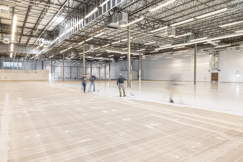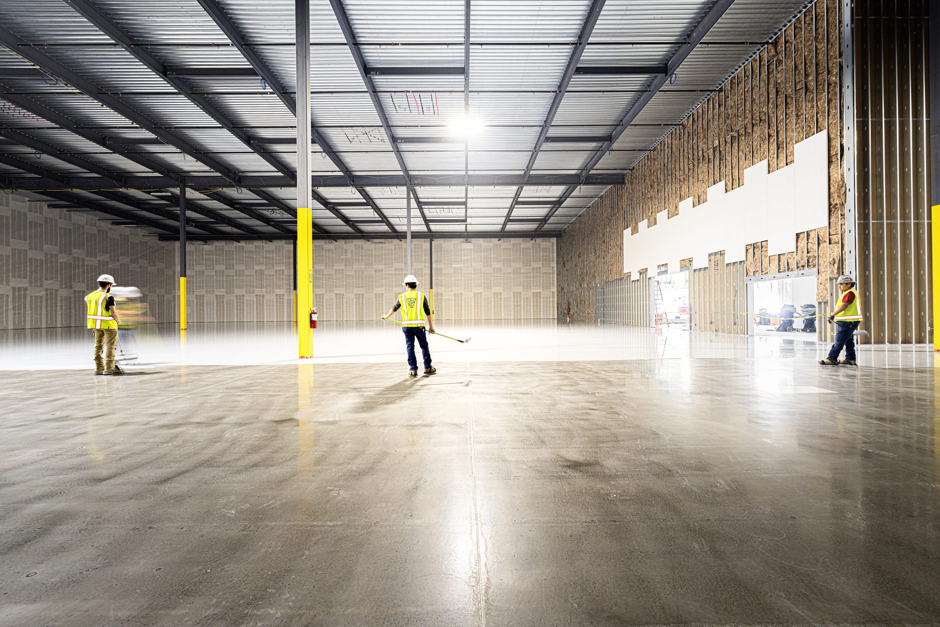
What can we help you with?
Technical flooring, delivered directly
- ESD flooring, urethane cement, terrazzo, and polished concrete
- In-house W-2 installation crews and experienced field leadership
- National service coverage with project-specific staffing plans
- Testing, documentation, and defined project closeout
- Dedicated support for corporate procurement and multi-site contracting
Phone: +1 (844) 687-1961
ESD Installation Steps at a Glance
Craftsman Concrete Floors provides ESD flooring installation with our own W-2 crews, from substrate preparation through grounding, coating application and assigned acceptance testing. We plan the work around the selected flooring system, the slab’s condition and the facility’s operating schedule.
The steps below explain our field work and the checkpoints required before the next step proceeds. Pre-bid assessment, scope development, procurement and approvals are covered in our project delivery framework.
| Step | Scope of work |
|---|---|
| 1. Substrate Evaluation, Repairs and Preparation | Confirm conditions, evaluate moisture, repair and prepare the slab. |
| 2. Priming | Apply the accepted standard or moisture-vapor-barrier primer. |
| 3. Grounding Components and ESD Coating Application | Install assigned connections and specified coating layers. |
| 4. Cure Conditions and Protection | Protect the work and track readiness for testing and traffic. |
| 5. Assigned Acceptance Testing | Measure, document and report against approved criteria. |
| 6. Release to Service and Handover | Review completed areas and provide handover evidence. |
The selected flooring system governs the detailed layer sequence. These steps describe the work and checkpoints; they are not a universal coating specification or a fixed-duration schedule.
Installation · Step 1 of 6
Substrate Evaluation, Repairs and Preparation
Confirm conditions, evaluate moisture, repair and prepare the slab
What This Step Covers
Craftsman confirms the available work area and checks the substrate against the conditions recorded during the pre-bid assessment. We identify exposed damage, existing coatings, contamination and other conditions requiring attention before the selected flooring system is applied.
How It Works
We coordinate the specified moisture evaluation and compare the results with the selected manufacturer’s limits. Existing pre-bid results are reviewed for their relevance to the installation plan. If findings require a different preparation or moisture-control approach, Craftsman documents the issue and coordinates the technical and commercial decision before implementing the recommended change.
Our crews complete the specified repairs and joint treatment, then mechanically prepare the slab to the required surface profile. Shot blasting or another specified preparation method follows the selected system’s instructions. We document unresolved conditions before advancing the work.
Coordination: The facility provides access to the released work area. Craftsman coordinates any newly discovered condition affecting the agreed scope with the authorized project contact.
What may vary: Concealed damage, contamination or moisture results may change the repair, preparation or primer selection. Moisture above the selected manufacturer’s limits may call for a moisture-vapor-barrier primer, which costs more than standard primer. Craftsman documents the finding and obtains technical and commercial approval before changed work begins.
Installation · Step 2 of 6
Priming
Apply the accepted standard or moisture-vapor-barrier primer
What This Step Covers
Priming is required in this installation workflow. The selected flooring system, substrate findings and accepted installation plan determine whether crews apply standard primer or a compatible moisture-vapor-barrier primer in its place. The barrier primer replaces standard primer in this sequence; it is not an additional primer layer. A moisture result outside the selected manufacturer’s limits triggers review before application.
How It Works
Our crews apply the approved primer at the specified coverage and thickness, observe its product-specific recoat and cure conditions, and record the product and treated area. Because a moisture-vapor-barrier primer costs more than standard primer, any resulting price or schedule change requires technical and commercial approval before application.
Coordination: Craftsman reviews the primer choice with the authorized project contact and obtains required technical and commercial approval before a changed application.
What may vary: Moisture results, substrate condition and product compatibility can require a moisture-vapor-barrier primer instead of standard primer. The selected product’s preparation, coverage and recoat requirements may change the agreed price or schedule.
Installation · Step 3 of 6
Grounding Components and ESD Coating Application
Install assigned connections and specified coating layers
What This Step Covers
Craftsman installs the grounding components and coating layers required by the selected flooring system. We follow its connection locations, layer sequence, coverage rates and film-thickness requirements. Conductive primers and copper-tape arrangements are used where specified for that system.
How It Works
We coordinate designated connection points with the responsible project parties and document the grounding work assigned to our crews. Grounding tape and connection points must remain intact through installation and testing; the facility coordinates protection from damage or removal by other trades. The qualified party assigned to the electrical work verifies the building grounding reference. Craftsman records the reference used for floor-resistance testing.
Our crews complete required in-process inspections before subsequent coats cover the work. These can include grounding details, applied thickness and intermediate electrical checks where the manufacturer requires them. Product-specific details are available in our RESUFLOR SCT and Sikafloor ESD guides.
Coordination: Craftsman confirms connection locations with the assigned project parties; the facility communicates protection requirements to other trades.
What may vary: The selected flooring system can require different grounding locations, coating layers and checks before coverage. Damaged or removed connection points require review and repair before acceptance testing.
Installation · Step 4 of 6
Cure Conditions and Protection
Protect the work and track readiness for testing and traffic
What This Step Covers
Craftsman schedules successive coats and the final cure around the selected products’ instructions and recorded site conditions. We distinguish the time needed to apply another coat from readiness for acceptance testing and release to foot or equipment traffic.
How It Works
We coordinate protection of the installed areas with the facility team and identify restrictions that remain in place while the system cures. The schedule allows for the required preparation or cleaning before testing. Our acceptance-test timing guidance explains why intermediate checks, final readings and traffic release are separate milestones.
Coordination: Craftsman communicates area restrictions and readiness status; the facility coordinates other trades and operational access with the agreed plan.
What may vary: Temperature, relative humidity and airflow can affect recoat and cure timing under the selected product’s instructions. Fans or other airflow controls are used only when compatible with that product and the approved site plan; they do not establish a universal shorter cure period.
Installation · Step 5 of 6
Assigned Acceptance Testing
Measure, document and report against approved criteria
What This Step Covers
When specified, Craftsman employees perform ANSI/ESD STM7.1-2020 installed-floor acceptance testing after the required cure and manufacturer-recommended preparation. We measure resistance to ground and point-to-point resistance at mapped locations using a calibrated Desco 19290 meter kit and electrodes meeting the method’s requirements.
How It Works
We report results against the project’s approved acceptance criteria and document required conditions, instrument information and corrective work or dated retests. Our report provides installed-floor resistance evidence; it does not by itself certify the facility’s ESD program.
Where ANSI/ESD STM97.1-2025 system-resistance testing or ANSI/ESD STM97.2-2016 walking-body-voltage testing is required, Craftsman coordinates the separately assigned responsibilities and reports. Those tests evaluate the person, footwear and flooring combination. Our testing hub explains the available methods and their different roles.
Coordination: The approved test plan establishes who performs each test and who reviews the results. Craftsman confirms these assignments before the work reaches acceptance testing.
What may vary: The selected system’s cure condition, required cleaning and the approved test scope determine when readings can begin. Areas needing corrective work or retesting remain subject to the agreed acceptance process.
Installation · Step 6 of 6
Release to Service and Handover
Review completed areas and provide handover evidence
What This Step Covers
Craftsman reviews each completed area with the designated facilities representative or project manager. We confirm the agreed release conditions, provide the evidence supporting acceptance, and document punch-list items and any restrictions that remain. Phased projects can hand back areas individually where the approved plan permits it.
How It Works
We connect the preparation, grounding, in-process checks and acceptance results through consistent area identifiers. Craftsman supplies the applicable care instructions and accepted testing baseline, then completes the document package under the agreed project delivery and closeout process.
Our crews coordinate work-zone boundaries, containment, housekeeping and access around adjacent operations throughout the installation. The 34,000-square-foot Dallas installation provides a separate example of phased work in occupied space.
Coordination: Your authorized representative accepts the area under the project’s agreed procedure. Testing readiness and operational release remain separate decisions.
What may vary: Phased areas can reach acceptance at different times, and punch-list work or outstanding reports can affect each area’s release. The project’s approved handover procedure controls the decision.
Installation · Example Schedule
Example Project Timeline
Individual activity durations, not a total installation period
What This Covers
The following durations come from a representative 29,000-square-foot electronics assembly and QA lab with nearly 6,000 linear feet of joint repair. They describe individual activities, not a guaranteed total installation period.
How We Set the Schedule
Craftsman confirms the overall schedule after reviewing the required work and available installation windows. Moisture-test periods, material lead times, overlapping activities, remaining coats and acceptance requirements must also be accounted for; adding the example durations alone does not establish a completion date.
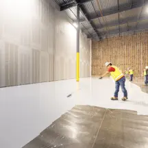
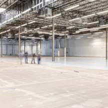
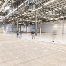
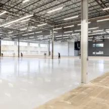
ESD Flooring Gallery


Frequently Asked Questions
Craftsman reviews the slab and selected system, coordinates required moisture evaluation, repairs and prepares the substrate, applies the required primer, then installs the specified grounding arrangement and coating layers. Our crews complete the manufacturer’s required checks between steps. Assigned acceptance testing and closeout follow the required cure period.
Craftsman follows the selected system’s grounding design and installs the connections assigned to our work. We record their locations and the reference used for floor-resistance testing. The project identifies the qualified party responsible for verifying the building grounding reference.
Craftsman sets the schedule after reviewing the slab, selected system and available work windows. In the 29,000-square-foot example, joint repair took about three days, shot blasting two days, and the barrier coat one day plus overnight cure. Those activities do not establish the total duration: remaining coats, moisture evaluation, cure, testing and any overlap must also be accounted for.
Yes, where the facility can release suitable work areas and the selected system and schedule support phased installation. Craftsman coordinates work-zone boundaries, access routes, installation controls and handback milestones with the facility team. Night and weekend work can be included in the agreed schedule.
When specified, Craftsman provides mapped resistance-to-ground and point-to-point measurements under ANSI/ESD STM7.1-2020, together with the required test conditions and pass/fail results against the project’s criteria. We include the assigned report and applicable corrective-work and retest records in closeout.
The selected manufacturer’s cure instructions and approved test plan determine the timing. Craftsman distinguishes intermediate product checks from final acceptance readings and confirms the preparation required before measurements. Release to foot or equipment traffic is a separate milestone.
Craftsman installs ESD flooring nationwide using our own W-2 crews, with an on-site skilled foreman supervising every installation shift. We assign project resources according to system experience, location, schedule and availability.
ESD Flooring Installation Process Knowledge Center
Project Planning & Delivery
Compliance Requirements & Testing
Systems & Selection
Where ESD Flooring Is Used
Maintenance and corrective work
Manufacturer ESD Flooring Systems
Case Studies
Craftsman Publishes 2026–2027 ESD Flooring Technical Guide
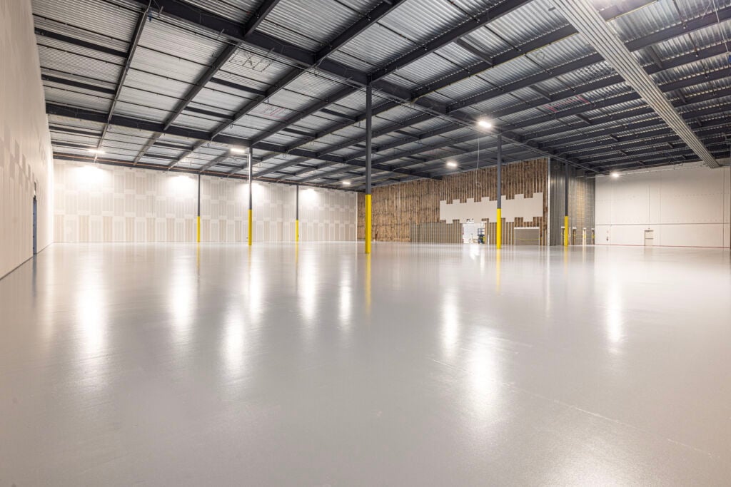
ESD Epoxy Flooring Case Study: 34,000 SF Dallas, TX