ANSI/ESD S20.20 + IEC 61340 COMPLIANCE
STANDARDS-DRIVEN INSTALLATION, TESTING & VERIFICATION
Every ESD flooring system we install is designed, tested, and documented to ANSI/ESD S20.20 and IEC 61340-5-1. These standards govern our material selection, grounding design, resistance classification, and post-installation verification.
Material systems are specified based on the electrical performance requirements of the environment — conductive (< 1.0 × 10⁶ ohms) for exposed-component handling, dissipative (1.0 × 10⁶ to 1.0 × 10⁹ ohms) for general ESD-protected areas. System selection is matched to the facility’s operational profile and component sensitivity thresholds.
Testing is performed per the standard’s referenced test methods — STM 7.1 for resistance-to-ground and point-to-point resistance, STM 97.1 for walking body voltage generation. Every measurement is taken with calibrated instrumentation, documented with environmental conditions, and mapped to floor plan locations. The result is an audit-defensible compliance record, not a summary letter.
- ANSI/ESD S20.20 program-level compliance
- IEC 61340-5-1 international compliance (dual-standard capable)
- Resistance-to-ground testing per STM 7.1
- Point-to-point resistance testing per STM 7.1
- Walking body voltage testing per STM 97.1
- Grounding system design + connection verification
- Conductive and dissipative system specification
- Calibrated instrumentation with traceability certificates
- Component-specific HBM sensitivity matching
NATIONWIDE MOBILIZATION
IN-HOUSE W-2 CREWS
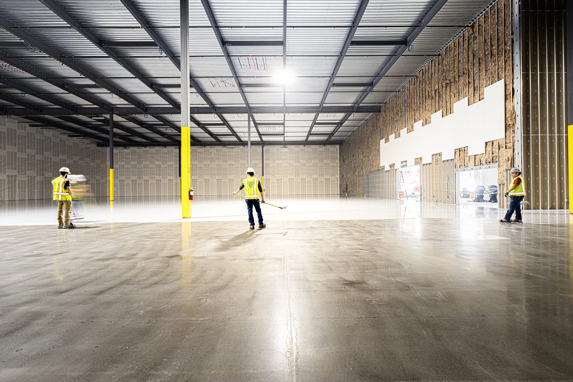
Our installation crews are in-house W-2 employees. The crew that installs in Virginia is drawn from the same workforce as the crew in Texas. Training, methods, and quality standards are consistent across every deployment. We maintain an EMR consistent with the safety requirements of heavy industrial and nuclear environments. Safety planning is site-specific, not generic.
Mobilization is managed via a centralized operations center that oversees logistics, QA, and financial controls with enterprise-level rigor. Every deployment follows the same protocol: pre-construction coordination, crew and equipment staging, material logistics, and site-specific safety planning — completed before the crew arrives on site.
We regularly deploy to remote and non-urban project sites — nuclear facilities, rural data center campuses, battery plants in areas without established specialty flooring infrastructure. The traveling crew model means geography isn’t a constraint on installer qualification.
Equipment travels with the crew. Grinders, shot blasters, HEPA vacuums, and testing instrumentation are owned — not rented locally. No calibration unknowns and no delays waiting on equipment availability.
- In-house W-2 crews
- Dallas-based operations center with centralized dispatch
- Former Fortune 500 COO overseeing operations
- Experienced field superintendent on every project
- Owned equipment fleet (grinders, shot blasters, testing)
- Material logistics coordinated with national suppliers
- Remote and non-urban site deployment capability
- Crew housing and rotation management for extended projects
- Second and third shift staffing available
MULTI-SITE PROGRAM EXECUTION + MSA
ONE SPECIFICATION, ONE VENDOR, EVERY FACILITY
A Master Service Agreement establishes the specification, pricing structure, documentation format, and quality standards once — then we execute consistently across every facility in the program. The floor in Building 12 matches Building 1 because the spec, the crew, and the QA process are the same.
Program-level consistency means one material system, one surface prep method, one testing protocol, and one documentation format across your entire portfolio. Your facilities engineering team reviews one format, procurement manages one vendor, and commissioning knows exactly what to expect at handoff.
Standardized rate structures provide budget predictability across your portfolio. Unit pricing is established by system type and project parameters at the program level, so your estimating team can carry accurate flooring costs on every new facility without waiting for site-specific bids. Adjustments for site conditions are handled through defined change protocols.
MSA clients receive priority scheduling with committed crew allocation. For operators building on compressed timelines, this means crew availability is secured when your schedule requires mobilization.
- Single specification across all program facilities
- Standardized unit pricing by system type
- Consistent documentation format across sites
- Dedicated crew allocation + priority scheduling
- Program-level QA/QC oversight
- Centralized project management + reporting
- Defined change order and site-condition protocols
- Periodic ESD recertification services
- Maintenance and lifecycle program available
ACTIVE-FACILITY + SHUTDOWN-WINDOW PHASING
INSTALLATION SEQUENCED AROUND LIVE OPERATIONS
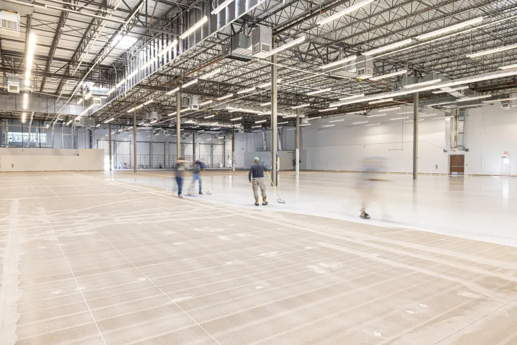
Most ESD flooring installations happen in facilities that are either actively operating or have adjacent operations that can’t be interrupted. Server halls with live equipment next door. Production lines running in the adjacent bay. Control rooms that never go offline. Installation sequences are designed around those operational constraints.
Phasing plans are developed during pre-construction in coordination with the facility operations team. Work zones, containment boundaries, access protocols, and sequencing are defined to keep installation isolated from operations. This includes HEPA-filtered containment during grinding and shot blasting, negative-pressure enclosures where required, and vibration-restricted work zones near sensitive equipment.
Shutdown-window work is scheduled to maximize flooring scope completed within available downtime — whether that’s a planned maintenance outage, a holiday shutdown, or a weekend window. Materials and equipment are pre-staged so that when the window opens, the crew is installing.
Occupied-space coordination includes daily communication with the facilities or operations team, defined check-in protocols, and documented work boundaries. Every day’s scope is communicated in advance and confirmed at completion.
- Phased installation sequencing per facility ops requirements
- HEPA-filtered containment during surface preparation
- Negative-pressure enclosures (adjacent to live environments)
- Vibration-restricted work zones
- Shutdown-window scheduling + pre-staged mobilization
- Weekend and off-hours installation capability
- Daily ops coordination protocol
- NOC / production team communication interface
- Work-zone isolation and access control
FULL SUBMITTAL + TESTING + CLOSEOUT DOCUMENTATION
STRUCTURED FOR YOUR RECORDS SYSTEM
Every project includes a complete documentation package covering the full lifecycle from pre-installation substrate testing through post-installation commissioning verification. Packages are structured to integrate with your document management system, audit requirements, and facilities records format.
Submittals are assembled for single-pass approval. Product data sheets, manufacturer approvals, installation procedures, safety plans, QA/QC plans, and phasing schedules are compiled into a complete submittal package before installation begins.
Testing documentation maps every result to a physical location on the floor plan. Resistance-to-ground, point-to-point, body voltage generation, moisture readings, surface profile measurements — each data point is tied to coordinates on the as-built drawing. An auditor can select any area on the floor plan and trace it back to its test results, material batch, and installer.
Closeout packages are delivered in the format you require — structured PDF, Procore upload, integration with your DMS, or hard-copy binders. Every test result, material certificate, warranty registration, as-built drawing, and maintenance guide is organized, indexed, and delivered as a complete record. For nuclear and DOE environments, documentation is structured for 30+ year retention and NRC-inspection readiness.
- Pre-installation moisture testing (ASTM F2170 / F1869)
- Surface profile documentation (ICRI 310.2)
- Complete product submittals with manufacturer approvals
- Project-specific QA/QC plan
- Installation phasing schedule
- Daily progress reports with photography
- Environmental condition logs (temp, RH, dew point)
- Material batch and lot tracking
- Resistance testing results mapped to floor plan (STM 7.1)
- Body voltage testing results (STM 97.1)
- Grounding verification records
- Manufacturer warranty certificates
- As-built documentation
- Maintenance and care guide
Request a Proposal
Submit project parameters for preliminary analysis. Commercial estimates typically returned within 24 hours.
ESD Flooring Knowledge Center
Resource links
Project Delivery Framework
Facility-Specific Requirements
Compliance & Testing Standards
Capabilities
ESD Systems & Selection
Installation & Maintenance
Case Studies
ESD Epoxy Flooring Case Study: 34,000 SF Dallas, TX
ESD Epoxy Flooring Case Study: 67,000 SF | Houston, TX