What can we help you with?
Technical flooring, delivered directly
- ESD flooring, urethane cement, terrazzo, and polished concrete
- In-house W-2 installation crews and experienced field leadership
- National service coverage with project-specific staffing plans
- Testing, documentation, and defined project closeout
- Dedicated support for corporate procurement and multi-site contracting
Phone: +1 (844) 687-1961
Our Clients




















Conductive-Floor Acceptance Testing
An acceptable average does not excuse a failing individual reading. DA Pam 385-64, Ammunition and Explosives Safety Standards (24 July 2023), Appendix E-3, sets separate limits for the average of five resistance readings and for each individual reading. Both requirements apply.
Average and individual acceptance limits
- Source
- Appendix E-3
DA Pam 385-64, Appendix E-3, specifies:
| Acceptance requirement | Two-electrode test | One-electrode-to-ground test |
|---|---|---|
| Average of five readings | More than 25,000 ohms and less than 1,000,000 ohms | Greater than 25,000 ohms |
| Each individual reading | At least 10,000 ohms and no more than 5,000,000 ohms | At least 10,000 ohms and no more than 1,000,000 ohms |
The two-electrode average limits are strict: an average exactly at 25,000 ohms or 1,000,000 ohms does not meet that requirement. The individual-reading limits include their stated endpoints.
Two-electrode test
- Readings
- Five locations
- Spacing
- 3 feet
DA Pam 385-64 requires readings at five different locations on the conductive surface. Place the two electrodes 3 feet apart at each location, record the readings, and calculate their average.
One-electrode-to-ground test
- Readings
- Five to ground
Obtain five resistance readings to ground. Place one electrode at each test location on the conductive surface, with the meter leads connected to the electrode and the ground point.
Appendix E-3 recommends allowing approximately 5 seconds for meter stabilization before recording a resistance reading.
Required instrument and electrodes
- Source
- Appendix E-3
DA Pam 385-64, Appendix E-3, specifies:
- A calibrated ohmmeter operating at a nominal open-circuit output of 500 V dc, with a short-circuit current of 2.5 mA to 5 mA and nominal internal resistance of at least 100,000 ohms.
- Two weighted electrodes, each weighing 5 lb with a flat circular contact area 2½ inches in diameter.
- An aluminum or tin-foil contact surface 0.0005 to 0.001 inches thick, backed by rubber ¼ inch thick with a Shore Type A hardness between 40 and 60.
Before testing
DA Pam 385-64 permits electrical floor tests only when the room or area is free of exposed explosives and/or flammable gas mixtures.
For installation, renovation, and recurring inspection requirements, see our Army conductive-floor requirements guide.
Frequently asked questions
No. DA Pam 385-64 (24 July 2023), Appendix E-3, sets both average and individual-reading limits. For the two-electrode test, the five-reading average must be more than 25,000 ohms and less than 1,000,000 ohms, and each reading must be at least 10,000 ohms and no more than 5,000,000 ohms.
No. DA Pam 385-64 (24 July 2023) allows no individual reading above 1,000,000 ohms in the one-electrode-to-ground test. Each reading must also be at least 10,000 ohms, and the average of the five values must be greater than 25,000 ohms.
No. DA Pam 385-64 (24 July 2023) requires the two-electrode five-reading average to be more than 25,000 ohms and less than 1,000,000 ohms. An average exactly at either boundary does not meet that stated average requirement.
Blog

Craftsman Publishes 2026–2027 ESD Flooring Technical Guide
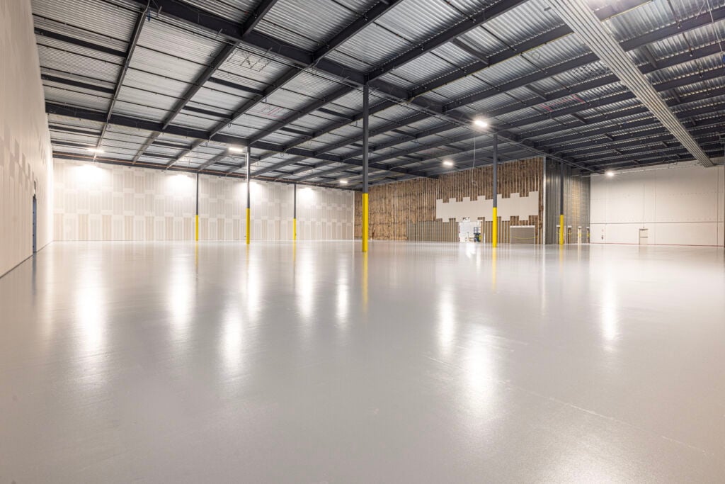
ESD Epoxy Flooring Case Study: 34,000 SF Dallas, TX