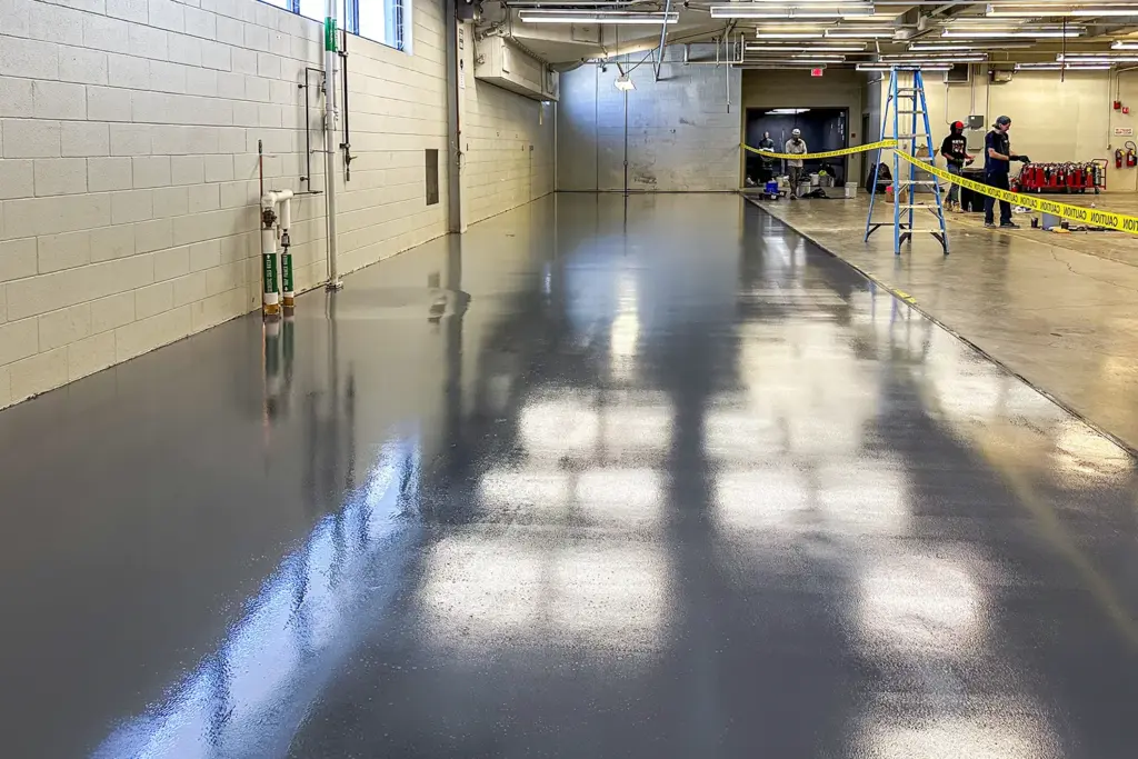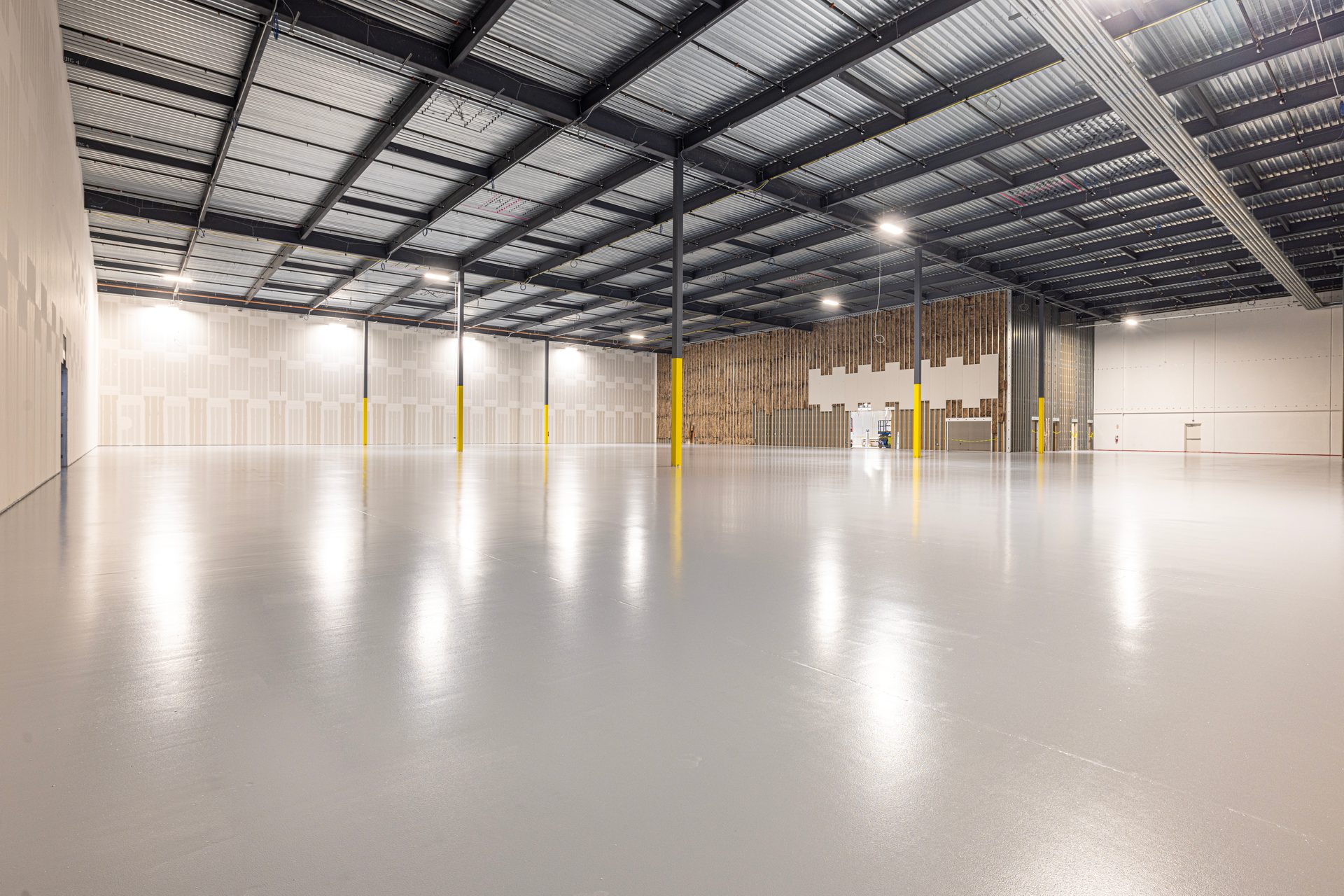
ESD epoxy, conductive, and chemical-resistant flooring systems for lithium-ion battery manufacturing, dry room environments, electrode production, and gigafactory facilities. ANSI/ESD S20.20 compliant. Installed nationwide.
- Systems: conductive and static dissipative ESD epoxy for battery manufacturing — Authorized SW + PIP + Sika installer
- Resistance:
- – Conductive: below 1.0 × 10⁶ ohms
- – Static dissipative: 1.0 × 10⁶ to 1.0 × 10⁹ ohms
- – Body voltage: under 100V per STM97.2
- Compliance:
- – ANSI/ESD S20.20 program standard
- – STM7.1 resistance testing
- – STM97.1 system resistance + STM97.2 body voltage testing
- – NFPA 70 Class I Division 2 review where flammable atmospheres are present
- Applications:
- – Electrode coating and calendering
- – Dry rooms and formation/aging areas
- – Cell assembly and module/pack lines
- Pricing: $3.34-13.55/sqft installed depending on system type, thickness, and substrate condition
- Installation: in-house W-2 crews; W-2 installers, not 1099 day-labor; phased ESD install around live operations; since 1999
- Deliverables: STM7.1 resistance logs, STM97.1 system resistance data, STM97.2 body voltage results, full S20.20 closeout package
Phone: +1 (844) 687-1961
Battery manufacturing ESD flooring carries two hazards on one slab: static discharge that damages cells and line electronics, and ignition risk from the solvents run across cell production. The carbonate electrolyte solvents such as DMC are flammable at close to room temperature, and the NMP slurry solvent at the electrode coating line is combustible and handled hot. Where a flammable atmosphere can form, the specification typically moves to the conductive band, below 1.0×10⁶ Ω, reviewed against NFPA 70 Class I Division 2. Craftsman Concrete Floors installs conductive and static dissipative ESD epoxy for lithium-ion cell plants, EV battery flooring programs, and gigafactory construction nationwide, each system verified to ANSI/ESD S20.20 before turnover. In-house W-2 crews have installed industrial floors since 1999.
The dry room compounds the static problem. At dew points below -40°C, triboelectric charging accelerates because there is no ambient humidity to bleed charge off people and equipment, so the grounded floor becomes the primary discharge path rather than a backup. The coating specification also has to tolerate the NMP slurry solvent at the electrode line, and the resistance band has to survive that chemical exposure without softening. Every install closes out with STM7.1 resistance logs, STM97.1 system resistance data, STM97.2 body voltage results under 100V, and a documentation package sized for OEM and tier-1 qualification audits.
Our Clients




















ESD Control and Ignition Risk in Cell Production
Battery plant ESD flooring is specified against two failure modes that rarely coexist elsewhere. A static event in cell assembly or formation damages product directly; a discharge near solvent vapor at the electrode line can ignite it. Which hazard governs each zone determines the floor class and the grounding architecture that follows. Over-specifying conductive plant-wide adds material cost; under-specifying near solvents is a code failure caught at the worst possible time, during electrical classification review.
Why Ignition Zones Default to the Conductive Band
Where flammable solvent vapor can be present, the floor typically must sit in the conductive band, below 1.0×10⁶ Ω, so charge drains to ground faster than it can accumulate to an incendive level. General electronics plants specify static dissipative flooring at 1.0×10⁶ to 1.0×10⁹ Ω as the default and reserve conductive flooring for exceptions, so a buyer arriving from an electronics spec should expect the band requirement to change on battery work. Electrical classification of the space, NFPA 70 Class I Division 2 in many electrode coating and electrolyte handling areas, drives the requirement alongside the facility’s ANSI/ESD S20.20 program. The full class-selection logic, including footwear pairing, lives on our conductive vs dissipative comparison page.
Solvent Exposure at the Electrode Coating Line
Electrode coating room flooring sees NMP slurry solvent and electrode slurry spatter that soften or stain coatings never formulated for chemical service. On battery work the chemical-exposure profile is written into the coating spec as a secondary requirement alongside the resistance band, and the two are checked together at submittal. Standard ESD epoxy fails the solvent exposure; standard chemical-resistant flooring fails the static requirement. The battery spec has to carry both, which narrows the qualified system list and makes the manufacturer data sheet review a submittal-stage task rather than an afterthought.
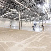
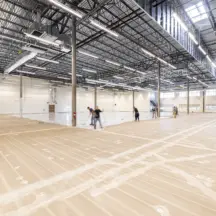
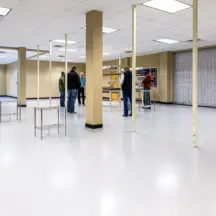
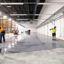
ESD Flooring Gallery

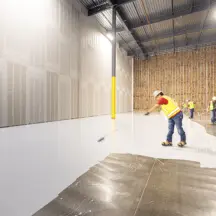
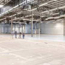
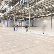
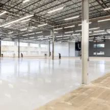
Request a Proposal
Dry Rooms and Zone-by-Zone Requirements
Dry Room ESD Flooring at Sub-Zero Dew Points
Dry room ESD flooring works against the worst static environment in the plant. At dew points below -40°C there is effectively no ambient humidity, so triboelectric charging on people, carts, and film runs far higher than in conditioned space and self-dissipation stops. The grounded floor becomes the primary control: a conductive or dissipative system tied to building steel through a conductive primer, verified per STM7.1 after the 24-72 hour cure-and-test window. Moisture contribution from the floor build-up itself is also reviewed in dry room submittals, since the room’s dehumidification load is sized against every material inside it.
Battery Manufacturing ESD Flooring, Zone by Zone
Lithium battery flooring requirements change zone by zone. Electrode coating and calendering carry the solvent and ignition load. Cell assembly and formation-and-aging areas are ESD-governed product-protection zones, closer to standard electronics practice. Module and pack lines add forklift traffic and point loads on top of the static requirement. A gigafactory ESD flooring package maps each zone to its band, its grounding detail, and its verification frequency, so one plant may run conductive floors at the coating line and dissipative floors through assembly. EV battery flooring programs at retrofit sites follow the same zoning logic, phased around live production.
Grounding, Verification, and Closeout
The Ground Path Is the Failure Point
Most failed ESD floors fail at the ground path, not the coating. A conductive primer thinned out of spec, ground straps spaced wrong, or a strap never tied to building steel leaves a floor that reads fine point-to-point and still cannot drain charge to ground. On battery plant ESD flooring the stakes are higher because a floating floor near solvent vapor is an ignition exposure on top of the yield problem. Craftsman installs the ground plane and straps to building steel, then verifies point-to-ground resistance per STM7.1 only after the 24-72 hour cure window, when readings are reliable.
S20.20 Verification and Audit Documentation
S20.20 compliant flooring is proven by test data, not by the product name on the drum. Closeout on a battery plant includes STM7.1 floor-material resistance logs mapped by zone, STM97.1 system resistance measured with the facility’s actual footwear, and STM97.2 body voltage results under the 100V program threshold. OEM and tier-1 qualification audits ask for exactly this package, and plants that cannot produce it re-test at their own cost. Our compliance-standards reference page covers each method in detail.
Phased Installation Around Live Cell Production
Phased zone-by-zone install around live operations is the default on retrofit battery work, with a 24-72 hour cure-and-test window before resistance verification per STM7.1. In-house W-2 crews provide national service coverage; W-2 installers, not 1099 day-labor, hold the schedule when a formation area can only come offline between builds. Lead time runs 1-3 weeks from contract execution, driven by material availability. At scale the model holds: our largest single ESD placement to date is a 67,000 sq ft phased install for a hyperscale-grade Houston facility, moisture-tested, resistance-verified, and closed out without stopping the client’s operation.
ESD Flooring Knowledge Center
Resource links
Where ESD Flooring Is Used
Compliance Requirements & Testing
- ESD Control Program Standards
- ESD Facility Requirements
- ESD Floor Retesting Services
- Humidity and conditioning by test method — Distinguish qualification conditions from installed-floor conditions when reviewing dry-room test records.
- STM7.1 laboratory conditioning — Review the low- and moderate-humidity stages used for flooring qualification samples.
- STM97.1 person–footwear–floor resistance — See what the system-resistance evaluation measures alongside floor-only results.
Systems & Selection
Project Planning & Delivery
Maintenance & Troubleshooting
Manufacturer ESD Flooring Systems
Frequently Asked Questions
Battery plant ESD flooring runs $3.34-13.55/sqft installed depending on system type, thickness, and substrate condition, derived from real bid data on 250+ commercial ESD projects. Conductive systems for solvent areas and chemical-exposure topcoats sit toward the upper half of the range. At gigafactory ESD flooring scale, unit pricing is driven down by continuous placement and up by phasing and dry room access constraints, so budget from a zone map rather than a single blended number.
Conductive, below 1.0×10⁶ Ω, wherever flammable solvent vapor can be present, including many electrode coating and electrolyte filling areas under NFPA 70 Class I Division 2 review. Static dissipative at 1.0×10⁶ to 1.0×10⁹ Ω is the default in cell assembly, formation, and pack areas where the hazard is product damage rather than ignition. Most plants run both bands zone by zone, and the full selection logic is on our conductive vs dissipative page.
Grounded ESD epoxy, conductive or dissipative to match the zone’s classification, grounded through a conductive primer and straps to building steel. At dew points below -40°C static generation runs higher than anywhere else in the plant because there is no ambient moisture to carry charge away, so the floor is the controlling discharge path. Resistance is verified per STM7.1 after the 24-72 hour cure-and-test window, and the floor build-up is reviewed against the room’s dehumidification load at submittal.
The facility’s ESD-control program and project documents define the required acceptance testing. When assigned, STM7.1 measures floor-material resistance, STM97.1 measures resistance through the floor-footwear-person system, and STM97.2 measures body-voltage generation. Testing occurs after the specified cure period. Craftsman delivers the test records required by the executed scope; no project automatically receives every method or document.
Lead time runs 1-3 weeks from contract execution, driven by material availability, with placement phased zone by zone around live production. Each zone needs the 24-72 hour cure-and-test window before resistance verification per STM7.1, so the schedule is built backward from when each area must return to service. Formation and dry room areas are typically sequenced last because their access and atmosphere constraints are tightest.
Yes. Craftsman provides national battery-manufacturing ESD flooring installation through directly employed W-2 crews assigned companywide for the actual project. Staffing, field leadership, equipment origins, travel assumptions, and schedule are project-specific; Craftsman’s offices are service and accountability points, not fixed workforce origins. A 67,000-square-foot ESD installation in Houston is a project-location example, not a statement that national crews originate in Houston or elsewhere in Texas.
Case Studies
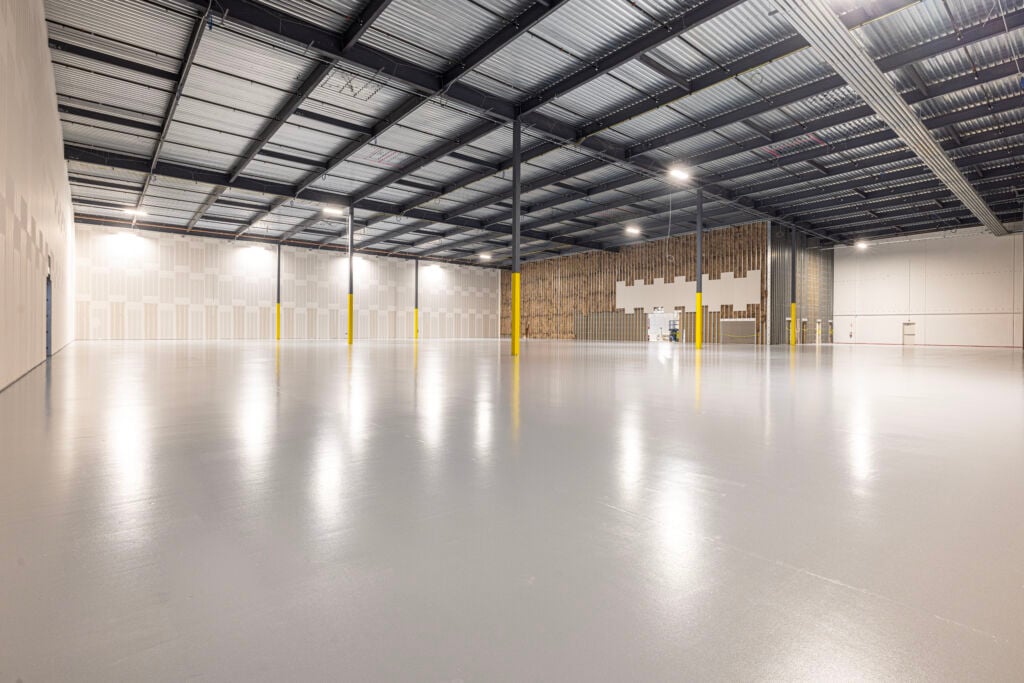
ESD Epoxy Flooring Case Study: 34,000 SF Dallas, TX
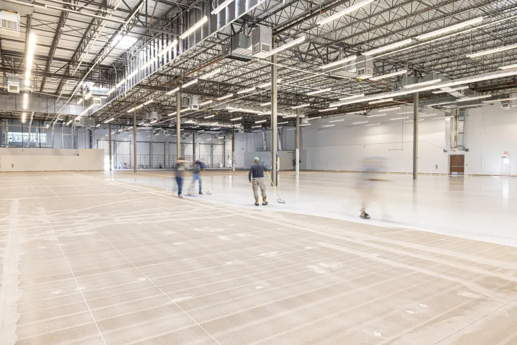
ESD Epoxy Flooring Case Study: 67,000 SF | Houston, TX