What can we help you with?
Technical flooring, delivered directly
- ESD flooring, urethane cement, terrazzo, and polished concrete
- In-house W-2 installation crews and experienced field leadership
- National service coverage with project-specific staffing plans
- Testing, documentation, and defined project closeout
- Dedicated support for corporate procurement and multi-site contracting
Phone: +1 (844) 687-1961
Our Clients




















Monitoring, Inspection, and Verification
Grounding monitors check electrical connections, but an interlock shutdown does not necessarily end static charge generation. Inspection, grounding-point verification, and operator training remain necessary parts of the work.
The guidance below comes from Newson Gale’s Grounding & Bonding Applications, Issue 4, including its quotations from IEC TS 60079-32-1. It forms part of static control in hazardous areas.
Interlocks and continued material movement
- Source
- Newson Gale guide
Newson Gale describes an interlocked system that can shut down one or both channels serving two independent plant items if the ground is lost. Its truck-mounted grounding example automatically shuts down product transfer when the ground connection is lost.
The product itself must stop moving to prevent further charge generation. Switching off a pump after a grounding connection is removed can leave material moving even though the machine has stopped.
Inspecting connections and verifying grounding points
- Records
- Results recorded
Newson Gale’s non-exhaustive safety checklist calls for regular inspection and maintenance of grounding straps, clamps, wires, and monitoring systems, with results recorded. For continuity testing where flammable products are handled, it says intrinsically safe equipment should be used.
Disassembly for cleaning or maintenance can lead to missed or incorrectly restored bonding connections. Flexing, vibration, and corrosion can also degrade connections.
Resistance in an all-metal earth path
- Source
- IEC TS 60079-32-1, 13.4.1
- Typical
- Less than 10 Ω
IEC TS 60079-32-1, section 13.4.1, as quoted in the guide, states that resistance in a continuous all-metal earth path is typically less than 10 Ω. Greater resistance usually indicates a discontinuity, commonly caused by loose connections or corrosion.
Grounding-point verification and operator training
- Responsible
- Site owner
Newson Gale assigns responsibility for the performance and condition of high integrity grounding points to the site owner. A site-appointed competent electrical person needs to verify them regularly.
Operators working in EX/HAZLOC areas should be trained in static electricity as a potential ignition source because they use the site’s grounding and bonding equipment day to day.
Checks for specific applications
Type C FIBC grounding systems
A Type C flexible intermediate bulk container (FIBC) grounding system checks contact between conductive threads and grounding points. Newson Gale says it does not validate bag condition or verify liner-to-thread continuity; bag suitability and general condition remain the site owner’s responsibility. See what Type C FIBC grounding systems verify.
Footwear testers
Newson Gale says footwear testers indicate whether resistance through the shoes is below the maximum permitted by the relevant standards. They do not establish full compliance. The footwear testing guide covers the conditions for using these testers.
Floor contact and contamination
- Source
- IEC TS 60079-32-1, 13.3.1.4
For portable conductive items grounded through floor contact, dirt or paint may raise leakage resistance enough to allow hazardous charging. IEC TS 60079-32-1, section 13.3.1.4, as quoted by Newson Gale, recommends alternative earthing where that increase is expected, such as a cable with a 10 Ω connection resistance between the cable and item. See floor contamination and grounding.
Frequently Asked Questions
Not necessarily. Newson Gale’s Grounding & Bonding Applications, Issue 4, explains that an interlock can stop process equipment when the ground is lost, but material may continue moving after the machine stops. The product itself needs to stop moving to prevent further charge generation.
IEC TS 60079-32-1, section 13.4.1, as quoted in Newson Gale’s Grounding & Bonding Applications, Issue 4, states that a continuous all-metal earth path typically has resistance below 10 Ω. A greater resistance usually indicates a discontinuity in the metal path, commonly caused by loose connections or corrosion.
Newson Gale’s Issue 4 guide assigns the performance and condition of high integrity grounding points to the site owner. It says a site-appointed competent electrical person needs to verify them regularly. Its non-exhaustive checklist also calls for regular inspection and maintenance of grounding straps, clamps, wires and monitoring systems, with recorded results.
Blog
Craftsman Publishes 2026–2027 ESD Flooring Technical Guide
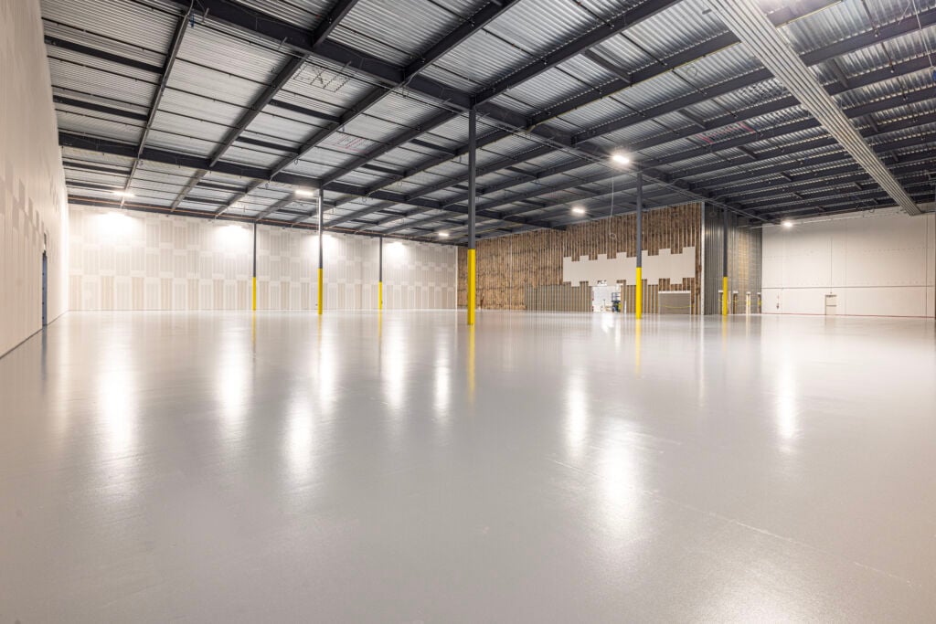
ESD Epoxy Flooring Case Study: 34,000 SF Dallas, TX